What is 2D design in Auto CAD?
2D design in AutoCAD refers to the process of creating two-dimensional digital drawings using AutoCAD software. AutoCAD is a computer-aided design (CAD) software that is widely used in the engineering, architecture, and construction industries. In 2D design, the user creates a flat representation of an object or project using lines, shapes, and text. The drawings can include various types of information, such as dimensions, annotations, and symbols. The software provides a range of tools and features that allow the user to create precise and accurate drawings.
Some common applications of 2D design in AutoCAD include creating floor plans, electrical schematics, mechanical drawings, and architectural blueprints. The software also allows for easy editing and modification of existing drawings, which can save time and improve productivity.
Overall, 2D design in AutoCAD is a powerful tool that allows designers and engineers to create detailed and accurate drawings for a wide range of applications.
2D designs are developed to create the idea of any manufacturing part or prototype before making it into reality. When it comes to 2D drawing software, the first thing that comes to our mind is AutoCAD.
AutoCAD was instrumental in popularizing Computer-Aided Design (CAD). To date, AutoCAD holds the top position in the industry when it comes to 2D drafting and architectural planning. Software tools like AutoCAD, SolidWorks, CATIA, and DraftSight are commonly used for creating 2D drafting for mechanical projects. However, it’s important to note that while 2D drafting is a valuable tool for conveying detailed information, many modern projects also incorporate 3D modeling and computer-aided design (CAD) techniques to create more comprehensive and interactive representations of mechanical designs.
Features of 2D drafting for mechanical projects include :
- Detailing: The drawings include precise measurements, dimensions, annotations, and labels to accurately represent the size, shape, and features of the mechanical components.
- Geometric Symbols and Notations: Standardized symbols and annotations are used to represent features such as holes, threads, surface finishes, and tolerances.
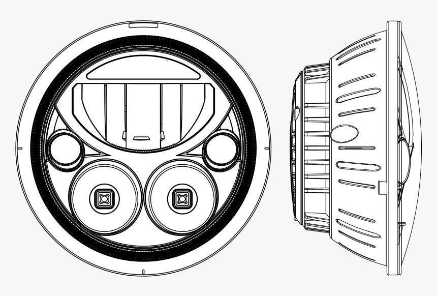
- Orthographic Views: Drawings often include multiple orthographic views (front, top, side, and sometimes isometric) to provide a comprehensive representation of the component or assembly from different perspectives.
- Section Views: These views cut through the component or assembly to reveal internal details that may not be visible in standard views, helping to convey complex structures.
- Bill of Materials (BOM): A list of all the parts and components required for the assembly, including part numbers, descriptions, quantities, and other relevant information.
- Assembly Drawings: When dealing with complex systems or machines, assembly drawings show how various components fit together and interact.
- Dimensioning and Tolerancing: Accurate measurements and tolerances are critical to ensure proper fit and functionality. Dimensions are indicated using appropriate techniques, such as linear dimensions, angular dimensions, and geometric tolerances.
- Title Blocks and Notes: Title blocks contain essential project information such as the project name, drawing number, revision history, and creation date. Notes provide additional information or instructions to clarify the drawing.
- Material Specifications: Drawings may include information about the material properties and specifications required for manufacturing the components.
Tips for 2D Drawing in AutoCAD.
Use the Snap feature to properly attach bodies.
If you are drawing a large portion, you can enable the grid option.
Make blocks for frequently used shapes.
If you are designing a sheet metal part like the one on this page, you can use the coordinate dimension instead of the linear dimension.
Create your custom one letter shortcuts for frequently used commands

2D Drawing

2d drafting : We use it for two purposes: Concept design and final manufacturing drawings. Our team is loaded with all CAD CAM and the latest technology software.
Our team understand all the technical criticality of the product and then our expert decide the process which we have to follow, we have expertise in various field like Plastic mold design, Sheetmetal tool design, Jig Fixture Design, Casting mold design(LPDC &HPDC mold), Rubber mold design(Compression, Transfer& Injection mold)
Our team has completed various Projects in these domains with timelines and quality of work for which we are known as Integrated Solutions.
